
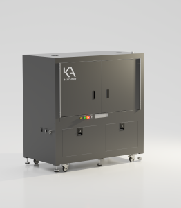
KA Imaging Launches Configurable Micro-CT System for Phase Contrast and Spectral Imaging

(Waterloo, Oct 1, 2024) Canadian X-ray manufacturer KA Imaging has announced the release of its inCiTe 2.0 3D X-ray Microscope, an innovative micro-CT system that integrates both phase contrast and spectral imaging capabilities. Designed for industrial and research applications, inCiTe 2.0 offers high-resolution imaging for non-destructive testing, making it an alternative to traditional Scanning Electron microscopy (SEM).

The inCiTe 2.0 Micro-CT system delivers multi-material differentiation in a single scan, optimizing material separation for industries such as aerospace, construction, and security. Its advanced phase contrast imaging technology enhances the visualization of low-density materials and subtle variations, offering a new level of detail and clarity in imaging applications.

“With inCiTe 2.0, we’re addressing the growing need for precise, high-quality imaging that can deliver detailed insights across a wide range of industries,” said Amol Karnick, president and CEO of KA Imaging. “This system’s ability to combine phase contrast and spectral imaging makes it an invaluable tool for both research and industrial applications, and it serves as a promising alternative to SEM in many cases,” added CTO Karim S. Karim.

For each X-ray exposure, inCiTe 2.0 captures dual-energy X-ray images, enhancing productivity by reducing the time and complexity typically required for multi-material inspections. This capability can benefit a variety of activities, including the inspection of components, battery technologies, and materials research.

Phase contrast imaging, a key feature of inCiTe 2.0, allows the system to better detect features with weak X-ray absorption that are often missed in conventional X-rays. Fine structures and soft materials, such as polymers, biological tissues, and composites, benefit from phase contrast imaging.

“By enabling researchers to visualize internal structures with exceptional clarity while maintaining material integrity, inCiTe 2.0 can also greatly benefit academic research,” said Technical Lead Chris Scott.

About KA Imaging

KA Imaging produces affordable, easy-to-use, high-resolution X-ray area detectors, flat panel detectors, and benchtop 3D phase contrast X-ray microscopes for medical, scientific, and industrial non-destructive testing (NDT) imaging applications.

Additional resources added October 2026. The press release above appears as originally issued on October 1, 2024.

Configurable Micro-CT for Phase Contrast and Spectral Imaging

Wanna learn more about our technology? This section explains what a configurable micro-CT system is, how phase contrast and spectral imaging work, and how to judge whether this kind of system suits your samples.

What is a configurable micro-CT system?

Micro-computed tomography (micro-CT) builds a 3D image of a sample’s internal structure. The sample rotates while hundreds or thousands of X-ray projections are recorded. Software then reconstructs them into a volume you can view slice by slice, without cutting the sample.

In many systems, the main hardware is fixed when the system is built. A configurable system is designed so that key parts can be chosen or changed to suit the sample. In practice, that usually means:

  • Detector. Some detectors are built for very fine spatial resolution. Others record energy information for spectral imaging, often with larger pixels and a wider field of view.
  • X-ray source. Higher tube voltages (kV) help X-rays pass through thicker or denser parts. A small focal spot supports fine detail and phase contrast, but it usually limits tube power.
  • Imaging geometry. The distances between the source, sample, and detector set the magnification. They also affect how strongly phase contrast appears.
  • Sample space. Extra room in the cabinet can hold in situ rigs that load, heat, or cool a sample during a scan.


A lab that images one type of sample may never need to change these settings. A lab that scans soft polymers one week and metal-containing assemblies the next may benefit from that flexibility.

How absorption, phase contrast, and spectral imaging work together


Absorption contrast: the starting point

Standard micro-CT measures how much X-ray intensity each part of the sample absorbs. It works well when materials absorb very differently, such as metal inside a polymer or pores inside a ceramic, and it remains the foundation of most micro-CT work. It has a harder time when materials absorb small, similar amounts. Polymers, foams, carbon fiber composites, and soft research samples can look nearly the same as each other.


Phase contrast: seeing weak absorbers and fine interfaces

X-rays behave like waves. As they pass through a material, some are absorbed, and the wave is also slightly shifted. This is called a phase shift. For materials made of light elements, the phase shift can be far larger than the absorption. That is why phase contrast can reveal materials that absorption shows poorly.

Detectors cannot record phase directly. Propagation-based phase contrast, also called in-line phase contrast, solves this with distance. With the detector placed some distance behind the sample, X-rays that bend slightly at an edge overlap with X-rays that passed straight through. This creates thin bright and dark fringes that outline boundaries. The method needs no gratings, but it does need a small focal spot and a detector fine enough to resolve the fringes. Software called phase retrieval can also turn these edge signals into smoother contrast across a region.

Phase contrast can help with:

  • Low-density materials such as polymers, foams, and light fibers
  • Boundaries between fibers and the surrounding matrix in composites
  • Thin layers, fine cracks, and delamination
  • Soft research samples that might otherwise need contrast staining


Phase contrast mainly highlights differences in density and sharp boundaries. On its own, it says little about what a material is made of.


Spectral (dual-energy) imaging: adding composition information

Two different materials can absorb the same amount of X-rays at one energy, so they look alike in a standard scan. They usually respond differently as the energy changes, because absorption by heavier elements drops more quickly as energy rises.

Spectral imaging records the X-ray signal in two or more energy ranges. It does this either by scanning more than once at different settings or with a detector that separates energy ranges during one exposure. Software compares the signals to create material maps or color overlays based on effective atomic number. These can help differentiate materials that look alike in a standard scan.

Spectral imaging also has limits:

  • It helps differentiate materials. It does not identify unknown materials on its own. Results depend on calibration, and confirming composition may still call for a method such as energy-dispersive X-ray spectroscopy (EDS).
  • Two energy ranges can reliably separate only a limited number of materials, typically two base materials at a time.
  • Material maps are usually noisier than the standard image, and artifacts such as beam hardening can affect accuracy.


Why combining the modes helps

Each mode answers a different question. Absorption shows overall structure and density. Phase contrast sharpens boundaries and fine features in weakly absorbing materials. Spectral imaging adds information about which regions are likely made of different materials. In a molded polymer part with metal contacts, for example, absorption shows the layout, phase contrast can sharpen fine polymer features, and spectral information can help separate the metal from the plastic. For a deeper look at both techniques, see how phase contrast and spectral imaging are expanding micro-CT capabilities.

Configurable or fixed benchtop micro-CT: which fits your lab?

A fixed benchtop system is compact and simpler to run, and it is often a strong choice when samples are small and similar. A configurable system adds choices, and with them more setup decisions and, often, more floor space.

A fixed benchtop system may suit you if...A configurable system may suit you if...
Your samples are similar in size and materialYour samples range from soft, low-density parts to dense or metal-containing parts
Fine structure matters more than compositionYou need both fine structure and information about composition
Lab space is limitedYou plan in situ experiments under load, heat, or other conditions
A few users run routine scansThe system serves several research groups or test programs

Practical considerations before you scan

Sample size and resolution. A detector has a fixed number of pixels. When the field of view grows to fit a larger sample, each voxel covers more of the sample, so the finest visible detail gets coarser. Very fine features often call for a smaller sample or a smaller region of interest.

Density, energy, and focal spot. Thick or dense samples need higher energies to get enough signal through. Higher energies also shrink absorption differences between light materials, which is one reason phase contrast and spectral information can help. Smaller focal spots support finer detail and phase contrast, but they usually run at lower power, which can mean longer exposures.

Scan time. Scan time depends on the number of projections, the exposure for each one, the resolution you need, and the imaging mode. Fine-detail scans, spectral acquisitions, and step-by-step in situ experiments often take longer than quick overview scans.

Mounting and sample sensitivity. Samples must stay still while they rotate, and in situ stages can limit how close the sample sits to the source. Some polymers and biological research samples can change with X-ray dose, so choose scan settings with the sample in mind.

Where configurable micro-CT is used

  • Composites: fiber orientation, voids, and delamination, where fibers and matrix may absorb X-rays in similar amounts.
  • Batteries: electrode structure, separators, and changes after charge cycling, viewed without opening the cell.
  • Polymers and foams: cell structure, porosity, and filler distribution.
  • Construction materials: pore networks, aggregates, and cracks in concrete and other cement-based materials.
  • Aerospace components: internal defects, inclusions, and bonded joints in lightweight, multi-material parts.
  • Academic research: in situ mechanical studies, materials development, and research samples such as biomaterial scaffolds.

How micro-CT fits alongside SEM

Scanning electron microscopy (SEM) shows surfaces in very fine detail and, with EDS, can measure elemental composition at the surface. Micro-CT shows internal structure in 3D without cutting the sample, usually at coarser resolution. Many labs use both: micro-CT first to locate internal features, then targeted sectioning and SEM where surface detail is needed. In many cases, micro-CT can reduce the need for destructive sectioning, but it does not replace SEM. Learn more in SEM vs. micro-CT: which inspection tool answers the right question.

inCiTe 2.0: KA Imaging’s configurable micro-CT system

The inCiTe™ 2.0 3D X-ray Microscope announced above is designed around this configurable approach. According to KA Imaging’s product page, it includes:

  • Two detector options: the BrillianSe™ hybrid pixel detector, which enables high spatial resolution, or the Reveal™ flat panel detector, which provides spectral imaging
  • A re-configurable modular design
  • A sealed X-ray source up to 150 kV, with spot sizes down to 2 µm (110 kV maximum)
  • Propagation-based phase contrast
  • Absorption, phase contrast, and spectral material decomposition imaging modes, with color-coding by atomic number designed to help differentiate materials
  • An expanded internal cabinet for custom in situ stages


For labs focused on small, low-density samples, KA Imaging also offers the benchtop inCiTe™ 3D X-ray Microscope with dedicated phase contrast.

To review full specifications, visit the inCiTe 2.0 product page. If you have a sample in mind, contact KA Imaging to talk it through.

Frequently asked questions

Does phase contrast micro-CT need a synchrotron?

No. Propagation-based phase contrast was first developed at synchrotrons, but it also works with laboratory X-ray tubes that have a small focal spot. Lab sources are less coherent than synchrotrons, so phase effects are usually weaker, but they can still improve the visibility of edges and weakly absorbing materials.

Dual-energy imaging is one type of spectral imaging. It uses two energy ranges. Some spectral systems, such as those with photon-counting detectors, sort X-rays into more energy bins. In both cases, the goal is to use energy information to help tell materials apart.

The terms overlap, and usage varies by manufacturer. Some reserve “X-ray microscope” for systems that add optical lenses behind a scintillator on top of geometric magnification. Others use it for high-resolution micro-CT systems in general. When comparing systems, look at measured spatial resolution, sample size limits, and contrast modes rather than the name.

In situ micro-CT scans a sample while it is held under a controlled condition, such as tension, compression, heating, or cooling. Repeated scans show how the internal structure changes, such as how a crack grows or pores collapse. This is sometimes called 4D micro-CT. It needs a stage that fits inside the system and still lets the sample be imaged from many angles.

Phase contrast offers the biggest gains for light, weakly absorbing materials and fine interfaces. In dense or metal-rich parts, absorption contrast is often already strong, so phase effects add less. Phase contrast can still sharpen the edges of lighter features inside a denser part, such as polymer layers or adhesive bonds.